
Integrated Permeate Channel Ultrafiltration membranes: Reference Water Reuse Installation at Carlsberg
Abstract
IPC® membranes are a special class of robust ultrafiltration membranes that are developed for Membrane Bioreactor applications but also have potential usage in difficult to treat feed waters. The main reason is the robustness of the product and the unique back-pulse at pressures up to 2 bar. Back-pulsing is a widely used technique in hollow fiber ultrafiltration membranes. In the case of IPC® membranes, the mechanical robust design and the large permeate channel allow for a good and efficient back-pulsing. This important and unique characteristic is the basis for serving our customers with the lowest cost of ownership.
1. Introduction
The IPC® membrane consists of an open 3D spacer fabric on which a polyvinylidene fluoride (PVDF) polymer solution is directly coated [1]. This unique production process creates a mechanical anchoring of the spacer fabric inside of the PVDF membrane layer and causes unparalleled robustness. In this paper, the use of the IPC® membrane modules in a large reference water reuse installation that is built and operated by Pantarein Water, is presented.
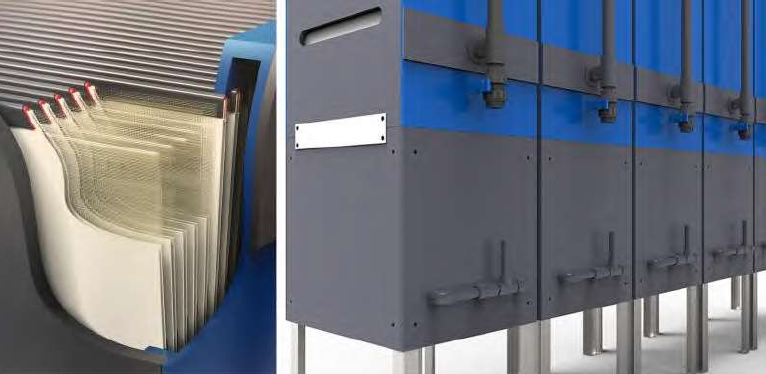
The IPC® membrane envelopes are potted in a modular and stackable module design (Figure 1). By combining the modules in height, double decks, triple decks and multi-modules are obtained where all permeate collection pipes are connected as one integral permeate extraction pipe. This has the advantage that all membranes, independent of their depth are operated with the same identical trans-membrane pressure (TMP) in both suction and backwash mode. One of the major advantages of the IPC® membrane technology is the ability to mechanically clean the membranes with a vigorous back pulse and to do an effective chemical enhanced backwash in place. Frequent backwash has proven by Ltiken et al [2]. to be a very effective way of removing cake from the membrane surface. This is very similar to the operation of hollow fiber submerged membranes with the one difference that the pressure drop is very homogeneous within the IPC® membrane envelope during backwash and that the aeration is being distributed very evenly over the whole membrane area. These aspects enable a wide and robust operational window and a very energy efficient operation.
The second part of this paper, a full-scale MBR operation at a brewery plant that was build by Pantarein Water (Belgium) is presented. The Carlsberg Group inaugurated a new, revolutionary plant that recycles 90% of the process water at its flagship brewery in Fredericia, Denmark on May 6, 2021. In the design of this water reuse facility, 90 % of process water from the production of beer and soft drinks will be recycled. This reuse of the treated water will result in a decrease of the water consumption from 2.9 hl of water per hl of beer today to 1.4 hl of water per hl of beer in the near future. This water reuse facility makes the Fredericia brewery the most water efficient in the world and brings Carlsberg one step closer to their ‘ZERO water waste’ goal. The robust IPC® membrane technology and plant design, enables direct reverse osmosis after the MBR filtrate 24/7.
2. CFD Modelling of Internal Back Pulse Pressure of IPC® Membranes
Computational Fluid Dynamics (CFD) is a technique that is frequently used nowadays to calculate flow distributions in water and wastewater systems [3]. In this example, CFD is used to model the backwash pressure inside of the IPC® envelope. The mechanical robustness of the IPC® membranes allows for back pulse at levated pressures up to 2 bar. In MBR operation, we advise to back pulse at a flow that equals two times the forwardflow (2 times the gross flux) for a short period of time (typical 15 to 30 sec) as part of the filtration cycle. The open structure of the permeate channel (2 mm) allows for a very even pressure pulse in the whole membrane envelope. The CFD modelling has simulated this pressure drop in a membrane envelope.
In Figure 2, the pressure loss during the back-pulse is calculated over IPC® membrane envelope. Under these conditions, Figure 2 shows a very even pressure distribution within the channel is obtained, only losing about 25- 30% of pressure at the far edges (point 4 and 4b on Figure 2) of the membrane envelope compared to the entrance of the two permeate manifolds (point 1 and 1d on Figure 2). This has several significant advantages and on both a membrane, module and MBR systems level which differentiate the IPC® membrane technology.
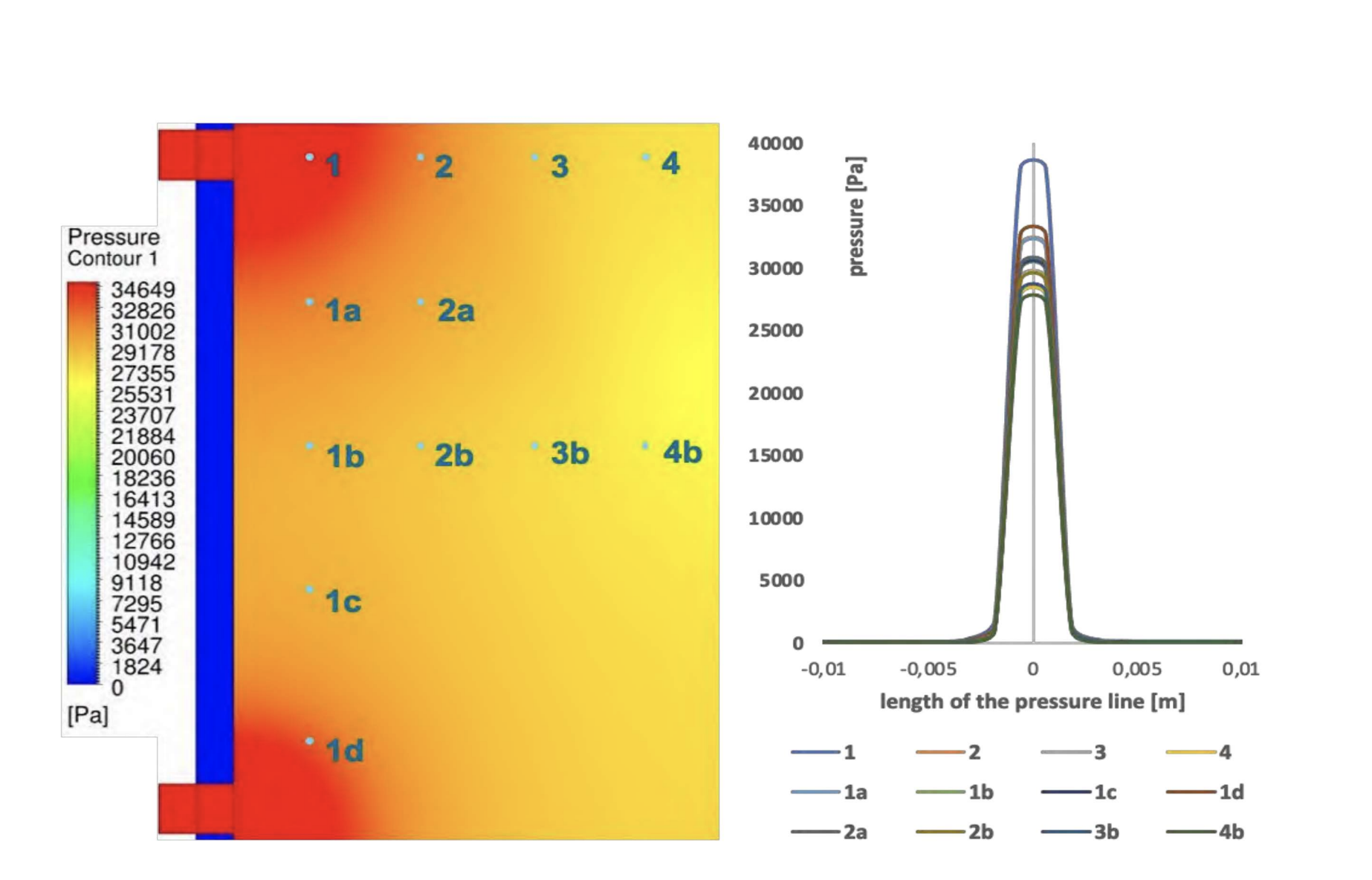
On a membrane level, the high pressure back pulse is possible even with high permeability membrane without losing the mechanical cleaning efficiency of backwash. This is a very effective pore-cleaning mechanism which is efficient over the whole membrane sheet. The same holds for chemical enhanced backwash (CEB) cleaning. Also, n this chemical cleaning operation, all pores will be chemically cleaned with the same volumetric flow of cleaning chemicals over the whole membrane sheet.
On a module level this characteristic is important because all membrane sheets have this same open connectivity to the permeate collection chamber whether the module is a stand-alone module, a double deck or a triple deck and will all be cleaned identically so this effective backwash works identically over the whole height of the module stack. On a systems level, the stable and effective mechanical and chemical cleaning method enables to clean the membranes in place, allows the use of significant BW pressure (up to 1 bar has been proven in large commercial installations as a form of test) and significant chemical cleaning concentrations without compromising the membrane/ module integrity or lifetime.
3. Full Scale Example and Advantages at Carlsberg, Fredericia (DK)
In Figure 3, the construction of a full-scale wastewater treatment and reuse plant for Carlsberg group in Fredericia (DK) is shown. In this operation, all these above-mentioned advantages of IPC® technology come together and express themselves in key performance attributes to the end-user as capacity/footprint at sustained elevated fluxes, low specific aeration demand per volume permeate produced (SADp) and low aeration energy need.
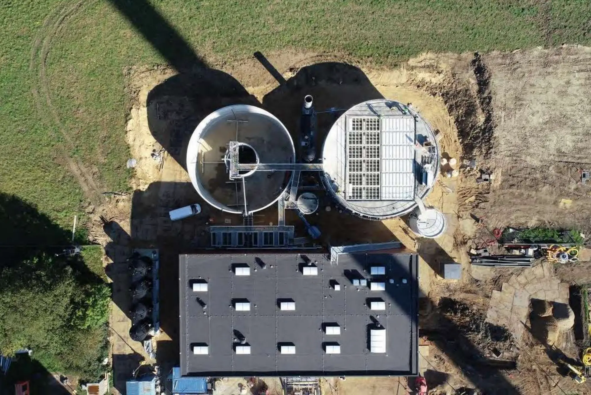
(Design and construction by Pantarein Water).
3.1 Process layout
The Fredericia plant treats process wastewater from brewery and soft drink production to drinking water quality water for recycling internally at the company. The installation can treat 750,000 cubic meters of wastewater per year. The treatment plant enables Carlsberg to reuse almost 90 percent of its process water and save 10 percent more energy. From the plant, the RO permeate water is used for all brewing applications; rinsing, cleaning the installations (CIP) and producing steam.
Inlet
The inlet pump is located at the inlet of the existing equalization tank and forwarded to the rotary fine screen with a 1mm hole size to remove particles from the process wastewater. To ensure a possible odor emission, the equalization tank is operated with a slight negative pressure, and the air is led to the central air purification. From this equalization tank, the process wastewater is pumped to the anaerobic process tank.
Biological Process
The anaerobic process is an upflow anaerobic sludge blanket (UASB) reactor. This system is operated in such a way that the bacteria form small high density spherical colonies. By this technique, developed by Pantarein water, the biomass is kept in the anaerobic process tank. The UASB reactor is operated at a significantly lower hydraulic residence time (6-12 hours) than a traditional hydraulic process tank. In this process, the dissolved readily degradable organic matter is converted to CH4 (70%) and CO2 (30%). The process is energy-producing and, 80- 90% of COD is removed without the use of oxygen.
The anoxic process tank is part of the aerobic process step. The purpose of the anoxic denitrification tank is to remove nitrate (NO3). This reduces the nitrogen content of the water and reduces energy consumption for the subsequent aerobic process. Nitrate is added by recirculation from the aerobic aeration tank. In the aerobic aeration tank, the remaining organic matter is converted into CO2.
Membrane Bio Reactor
For separation of the biomass in the aerobic process tanks and water, a membrane bioreactor (MBR) is used, containing 48 submerged IPC® membrane modules (Figure 4a). In this installation two membrane tanks with each 12 double deck IPC® membrane towers are installed. These membranes have a separation barrier with a membrane nominal pore size of 40nm, which is significantly smaller than the size of bacteria. This ensures that the purifying water will be bacteria-free.
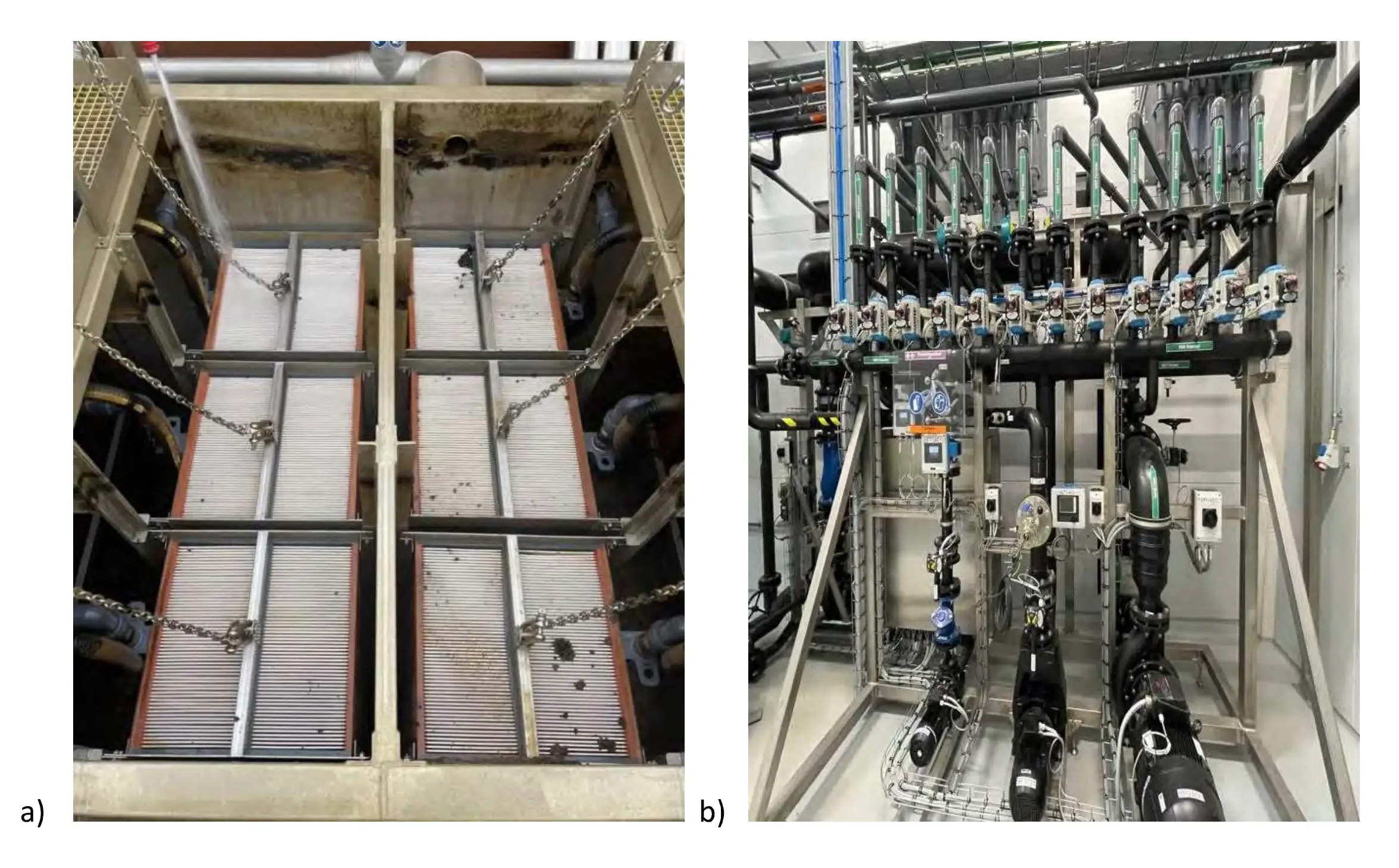
pumps of one MBR street [4].
The membrane is primarily cleaned by mechanical backwashing and air scour during the filtration operation. Periodically, in-situ cleaning by chemical enhanced backwash (CEB), is performed without removing the membranes from the filtration tank. In Figure 4b, the small backwash pump is shown as each tower is back pulsed individually during the production of the permeate.
The MBR operation produces over 100 m3 permeate/hour which is directly sent to the RO installation with by using a centrifugal pump that can give approximately 30 bar pressure at 100 m³/h [4].
CCRO – Closed Circuit Reverse Osmosis
The MBR does not retain salts and small molecular weight organics. These need to be removed before the treated water can be recycled. Reverse Osmosis (RO) membranes are used to remove salts and rest organic impurities to achieve high quality water that is required for recycling purposes in a number of recycling applications (rinsing, cleaning the installations (CIP) and producing steam).
3.2 MBR Operation using IPC® membranes
In January 2021 the water reuse plant was put into operation. It has a capacity of 100 m³/h and is expected to process about 750.000 m³ per year. Figure 5 shows that the gross permeate flow is 55 m³/h permeate. This is observed for both trains. The net permeate flow of 100 m³/h is produced using 24 double deck IPC® membrane modules with a total membrane area of 3650m³ membrane. Each of these double deck towers receive 48 Nm³/h Air. So, the total air volume rate over the 24 double decks is 1150 Nm³/h. As mentioned before, the effects of the backwash can be observed in this operation ad is shown in Figure 5 for Train 2 (with 12 double deck membrane modules): The net flux that is achieved is 27,4 |/m2.h at a TMP of 80mbar. The specific aeration demand (SADp) is the amount of air used (1150 Nm³/h) per volume of permeate (100 m³/h) equals 11,5 Nm³ Air /m³ permeate. In case of a triple deck, the SADp will be decreased with 30%.

Fredericia water reuse installation (Carlsberg, DK).
4. Conclusions
To conclude, the data presented above support that the characteristics of the Integrated Permeate Channel IPC®) membrane are unique and that IPC® membranes are a special class of robust ultrafiltration membranes or use in MBR application. The mechanical robustness and the unique back-pulse at pressures up to 2 bar delivers for the end-user a lower specific aeration demand and a high capacity per footprint. The treatment plant enables Carlsberg to reuse almost 90 percent of its process water and save 10 percent on energy and it makes the Fredericia brewery the most water efficient in the world and brings Carlsberg one step closer to their ‘ZERO water waste’ goal.
Acknowledgment
We are very grateful and acknowledge our partners for their contributions to this paper. Specifically, we thank AM Team for the fruitful discussion and CFD simulations and Pantarein Water for the availability of the full-scale data.
Abbreviations
| CCRO | Closed Circuit Reverse Osmosis |
| CEB | Chemical enhanced backwash |
| CFD | Computational fluid dynamics |
| IPC | Integrated permeate channel |
| MLSS | Mixed liquor suspended solids (mg/1I) |
| MBR | Membrane bioreactor |
| PVDF | Polyvinylidene fluoride |
| SADp | Specific aeration demand per volume permeate produced (Nm³/m³) |
| TMP | Transmembrane pressure (mbar) |
References
- W. Doyen, W. Mues, B. Molenberghs, B. Cobben, Desalination 2010, 250, 1078-1082. DOI: 10.2016/j.desal.2009.09.112
- A. Luiken, J. Linkhorst, R. Fréhlingsdorf, L. Lippert, D. Rommel, L. De Laporte, M. Wessling, Sci Rep 2020, 10, 20043,. https://doi.org/10.1038/s41598-020-76970-x
- I. Nopens, U. Rehman, in Advances in wastewater treatment (Eds: G.Mannina, G. Ekama, H. Odegaard, G. Olsson), IWA Publishing, London, UK 2018.
- Pump.nl, Pantarein bouwt de grootste waterzuivering bij Carlsberg, Issue 3, Juni 2021, pag. 48-50.